- /
- /
- /
Netgear Managed Switches
This example is on a GS108Tv1, but other Netgear models are all very similar if not identical. There are also several other vendors including Zyxel who sell switches made by the same manufacturer, using the same web interface with a different logo. Log into the web interface of the switch to start.
Planning the VLAN configuration
Before configuring the switch, several items are required:
- The number of VLANs to be configured
- The IDs to use for the VLANs
- How each switch port needs to be configured
For this example, an 8 port GS108Tv1 is used, and it will be configured as shown in Table 12: Netgear GS108T VLAN Configuration.
Table 12: Netgear GS108T VLAN Configuration
| Switch port | VLAN mode | VLAN assigned |
| 1 | trunk | 10 and 20, tagged |
| 2 | access | 10 untagged |
| 3 | access | 10 untagged |
| 4 | access | 10 untagged |
| 5 | access | 20 untagged |
| 6 | access | 20 untagged |
| 7 | access | 20 untagged |
| 8 | access | 20 untagged |
Enable 802.1Q VLANs
To configure the switch to use 802.1Q VLAN trunking:
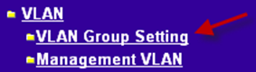
- Navigate to the System menu on the left side of the page
- Click VLAN Group Setting, as indicated in Figure 92: VLAN Group Setting.
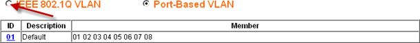
- Select IEEE 802.1Q VLAN (Figure 93: Enable 802.1Q VLANs).
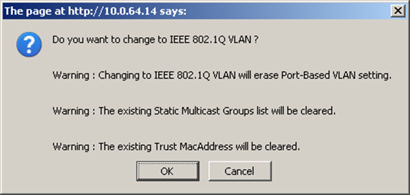
- Click OK to confirm the switch to 802.1Q trunking, as shown in Figure 94: Confirm change to 802.1Q VLAN.
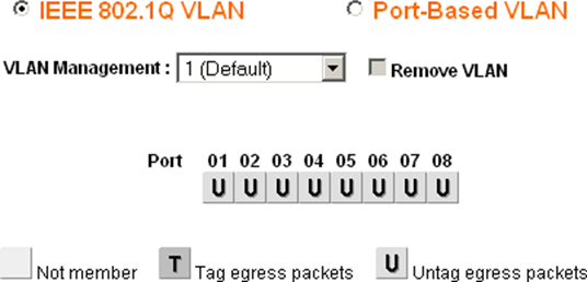
After clicking OK, the page will refresh with the 802.1Q VLAN configuration as shown in Figure 95: Default 802.1Q Configuration.
Add VLANs
For this example, two VLANs are added with IDs 10 and 20. To add a VLAN:
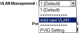
- Click the VLAN Management drop down
- Click Add New VLAN as shown in Figure 96: Add New VLAN.
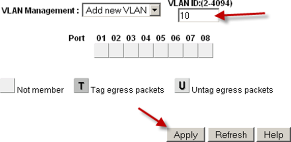
- Enter the VLAN ID for this new VLAN, such as 10
- Click Apply. The VLAN screen is now ready to configure VLAN 10 (Figure 97: Add VLAN 10).
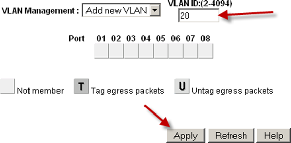
- Click Add New VLAN again as shown in Figure 96: Add New VLAN to add VLAN 20 (Figure 98: Add VLAN 20).
Add as many VLANs as needed, then continue to the next section.
Configure VLAN tagging
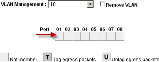
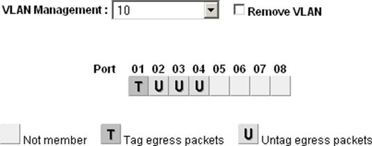
When a VLAN is selected from the VLAN Management drop down, it shows how that VLAN is configured on each port:
- A blank box means the port is not a member of the selected VLAN.
- A box containing T means the VLAN is sent on that port with the 802.1Q tag.
- U indicates the port is a member of that VLAN and it leaves the port untagged. The trunk port must have both VLANs added and tagged.
| Warning: Do not change the configuration of the port being used to access the web interface of the switch! This will lock the administrator out of the switch. The only means of recovery on the GS108Tv2 is using the reset to factory defaults button since it does not have a serial console. For the switches that have serial consoles, keep a null modem cable handy in case network connectivity with the switch is lost. Configuring the management VLAN is covered later in this section. |
Click in the boxes beneath the port number as shown in Figure ref:figure-toggle-vlan-membership to toggle between the three VLAN options.
Configure VLAN 10 membership
Figure 100: Configure VLAN 10 Membership shows VLAN 10 configured as outlined in Table table-netgear-gs108t-vlan- configuration. The access ports on this VLAN are set to untagged while the trunk port is set to tagged.
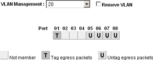
Configure VLAN 20 membership
Select 20 from the VLAN Management drop down to configure the port memberships for VLAN 20.
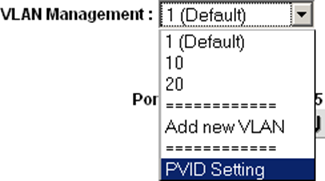
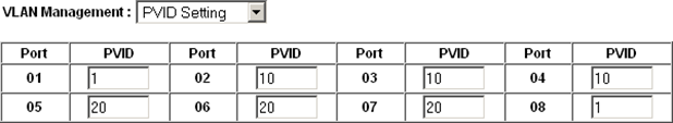
Change PVID
On Netgear switches, in addition to the previously configured tagging settings, the PVID must also be configured to specify the VLAN used for frames entering a port:
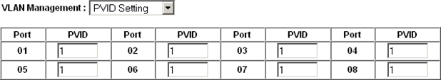
- Select PVID from the VLAN Management drop down as shown in Figure:102 PVID Setting.
The default PVID setting is VLAN 1 for all ports as shown in Figure 103: Default PVID Configuration.
- Change the PVID for each access port, but leave the trunk port and port used to access the switch management interface set to 1 .
Figure 104: VLAN 10 and 20 PVID Configuration shows the PVID configuration matching the port assignments shown in Table 12: Netgear GS108T VLAN Configuration, with port 8 being used to access the switch management interface.
- Apply changes when finished
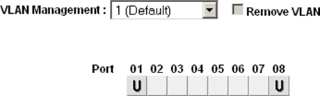
Remove VLAN 1 configuration
By default, all ports are members of VLAN 1 with untagged egress frames. To remove VLAN 1 from the other ports:
- Select 1 (Default) from the VLAN Management drop down
- Remove VLAN 1 from all ports except the one used to manage the switch and the trunk port, to avoid being disconnected.
In this example, port 8 is used to manage the switch. When finished, the screen will look like Figure 105: Remove VLAN 1 Membership.
- Apply changes when finished
Verify VLAN functionality
Configure VLANs on AZTCO-FW, including the DHCP server on the VLAN interfaces if needed. Plug systems into the configured access ports and test connectivity. If everything works as desired, continue to the next step. If things do not work as intended, review the tagging and PVID configuration on the switch, and the VLAN configuration and interface assignments on AZTCO-FW.