- /
- /
- /
Network Overview
The example network depicted here is a data center environment consisting of two AZTCO-FW firewalls with four inter- faces each: WAN, LAN, DBDMZ, and pfsync. This network contains a number of web and database servers. It is not based on any real network, but there are countless production deployments similar to this.
WAN Network
The WAN side connects to the upstream network, either the ISP, data center, or upstream router.
WEB Network
The WEB segment in this network uses the “LAN” interface but renamed. It contains web servers, so it has been named WEB but it could be called DMZ, SERVERS, or anything desired.
DBDMZ Network
This segment is an OPT interface and contains the database servers. It is common to segregate the web and database servers into two networks in hosting environments. The database servers typically do not require direct access from the Internet, and hence are less subject to compromise than web servers.
Sync Network
The Sync network in this diagram is used to replicate AZTCO-FW configuration changes via XML-RPC and for pfsync to replicate state table changes between the two firewalls. As described earlier in this chapter, a dedicated interface for this purpose is recommended.
Network Layout
Figure Diagram of HA with Routed IPs illustrates this network layout, including all routable IP addresses, the WEB network, and the Database DMZ.
Note: Segments containing database servers typically do not need to be publicly accessible, and hence would more commonly use private IP subnets, but the example illustrated here can be used regardless of the function of the two internal subnets.
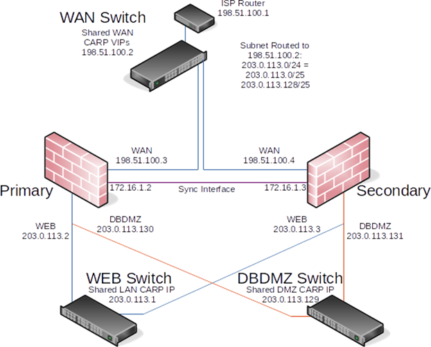
Fig. 10: Diagram of HA with Routed IPs