- /
- /
- /
Site-to-site example configuration
The key to making a working IPsec tunnel is to ensure that both sides have matching settings for authentication, encryption, and so on. Before starting, make a note of the local and remote WAN IP addresses, as well as the local and remote internal subnets that will be carried across the tunnel. An IP address from the remote subnet to ping is optional, but recommended to keep the tunnel alive. The firewall doesn’t check for replies, as any traffic initiated to an IP address on the remote network will trigger IPsec negotiation, so it doesn’t matter if the host actually responds or not as long as it is an IP address on the other side of the connection. Aside from the cosmetic tunnel Description and these pieces of information, the other connection settings will be identical.
In this example and some of the subsequent examples in this chapter, the following settings will be assumed:
Table 9: IPsec Endpoint Settings
| Site A | Site B | ||
| Name | Austin Office | Name | London Office |
| WAN IP | 198.51.100.3 | WAN IP | 203.0.113.5 |
| LAN Subnet | 10.3.0.0/24 | LAN Subnet | 10.5.0.0/24 |
| LAN IP | 10.3.0.1 | LAN IP | 10.5.0.1 |
Start with Site A. Create the tunnel by clicking + Add P1. The phase 1 configuration page for the tunnel is shown. Many of these settings may be left at their default values.
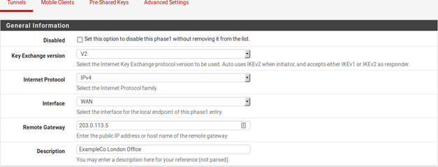
First, fill in the top section that holds the general phase 1 information, shown in Figure figure-vpn-tunnel-settings. Items in bold are required. Fill in the settings as described:
Disabled Uncheck this box so that the tunnel will be operational.
Key Exchange version Specifies whether to use IKEv1 or IKEv2. For this example, IKEv2 is used, but if one side does not support IKEv2, use IKEv1 instead.
Internet Protocol Will be IPv4 in most cases unless both WANs have IPv6, in which case either type may be used.
Interface Most likely set to WAN .
Remote Gateway The WAN address at Site B, 203.0.113.5 in this example.
Description Some text to state the purpose or identity of the tunnel. It is a good idea to put the name of Site B in this box, and some detail about the tunnel’s purpose to help with future administration. For this example ExampleCo London Office is used for the Description to identify where the tunnel terminates.
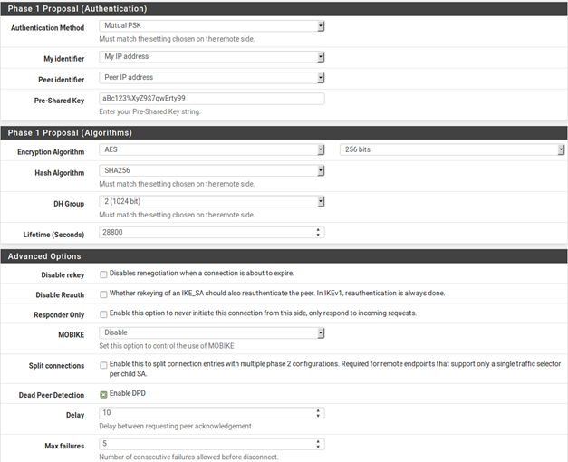
The next section controls IPsec phase 1, or Authentication. It is shown in Figure 44: Site A Phase 1 Settings. The defaults are desirable for most of these settings, and simplifies the process.
Authentication Method The default, Mutual PSK, is used for this example.
My Identifier The default, My IP Address, is kept.
Peer Identifier The default, Peer IP Address, is kept.
Pre-Shared Key This is the most important setting to get correct. As mentioned in the VPN overview, IPsec using pre-shared keys can be broken if a weak key is used. Use a strong key, at least 10 characters in length containing a mix of upper and lowercase letters, numbers and symbols. The same exact key will need to be entered into the tunnel configuration for Site B later, so note it down or copy and paste it elsewhere. Copy and paste may come in handy, especially with a complex key like aBc123%XyZ9$7qwErty99.
Encryption Algorithm Use AES with a key length of 256 bits.
Hash Algorithm Use SHA256 if both sides support it, otherwise use the default SHA1.
DH Group The default of 2 (1024 bit) is OK, higher values are more secure but use more CPU.
Lifetime May also be specified, otherwise the default value of 28800 will be used.
Disable rekey Leave unchecked
Responder only Leave unchecked
NAT Traversal Leave on Auto, since in this example neither firewall is behind NAT.
Dead Peer Detection Leave checked, the default Delay of 10 seconds and Max Failures of 5 is ade- quate. Depending on the needs at a site a higher value may be better, such as 30 seconds and 6 retries, but a problematic WAN connection on either side may make that too low.
Click Save to complete the phase 1 setup.
After the phase 1 has been added, add a new phase 2 definition to the VPN:
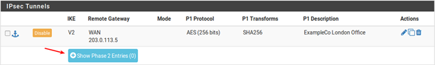
- Click
+ Show Phase 2 Entries as seen in Figure 45: Site A Phase 2 List (Empty) to expand the phase 2 list for this VPN.
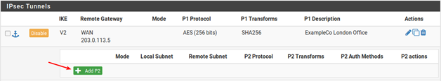
Click + Add P2 to add a new phase 2 entry, as seen in Figure 46: Adding a Phase 2 entry to Site A
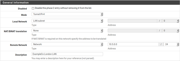
Now add settings for phase 2 on this VPN. The settings for phase 2 (Figure 47: Site A Phase 2 General Settings ) can vary more than phase 1.
Mode Since tunneling traffic is desired, select Tunnel IPv4
Local Subnet Best to leave this as LAN Subnet, but it could also be changed to Network with the proper subnet value filled in, in this case 10.3.0.0/24. Leaving it as LAN Subnet will ensure that if the network is renumbered, this end of the tunnel will follow. If that does happen, the other end must be changed manually.
NAT/BINAT Set to None.
Remote Subnet Set to the network at Site B, in this case 10.5.0.0/24.
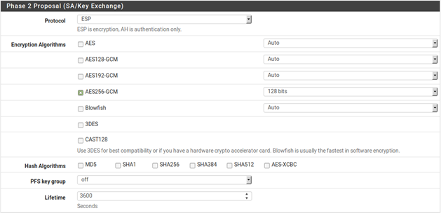
The remainder of the phase 2 settings, seen in Figure 48: Site A Phase 2 Settings , cover the encryption of the traffic. Encryption algorithms and Hash algorithms can both be set to allow multiple options in phase 2, and both sides will negotiate and agree upon the settings so long as each side has at least one of each in common. In some cases that may be a good thing, but it is usually better to restrict this to the single specific options desired on both sides.
Protocol Set to ESP for encryption.
Encryption algorithm Ideally, if both sides support it, select AES256-GCM with a 128 bit key length.
Otherwise, use AES 256, or whichever cipher both ends will support.
Hash algorithm With AES-GCM in use, no hash is required. Otherwise, use SHA 256 or SHA 1. Avoid
MD5 when possible.
PFS Perfect Forward Secrecy can help protect against certain key attacks, but is optional. In this example, it is disabled.
Lifetime Use 3600 for this example.
Lastly, an IP address can be entered for a system on the remote LAN that will be periodically sent an ICMP ping, as in Figure 49: Site A Keep Alive. The return value of the ping is not checked, this will only send traffic the tunnel so that it will stay established. In this setup, the LAN IP address of the AZTCO-FW firewall at Site B, 10.5.0.1, is used.

To finalize the settings and put them into action: * Click Save * Click Apply Changes on the IPsec Tunnels screen, as seen in Figure 50: Apply IPsec Settings

The tunnel for Site A is finished, but now firewall rules are needed to allow traffic from the network at Site B to enter through the IPsec tunnel. These rules must be added to the IPsec tab under Firewall Rules.
Rules may be as permissive as desired, (allow any protocol from anywhere to anywhere), or restrictive (allow TCP from a certain host on Site B to a certain host at Site A on a certain port). In each case, make sure the Source address(es) are Site B addresses, such as 10.5.0.0/24 . The destination addresses will be the Site A network, 10.3.0.0/24.
Now that Site A is configured, it is time to tackle Site B. Repeat the process on Site B’s endpoint to add a tunnel.
Only a few parts of this setup will differ from Site A as shown in Figure 51: Site B Phase 1 Settings and Figure 52: Site B Phase 2 Settings :
- The phase 1 settings for WAN address and Description
- The phase 2 tunnel networks
- The keep alive setting
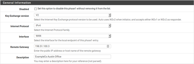
Add a Phase 1 to the Site B firewall using identical settings used on Site A but with the following differences:
Remote Gateway The WAN address at Site A, 198.51.100.3.
Description ExampleCo Austin Office.
- Click Save
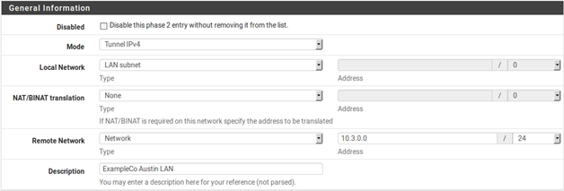
Add a phase 2 entry to the Site B firewall using identical settings used on Site A but with the following differences.
Remote Subnet The network at Site A, in this case 10.3.0.0/24.
Automatically ping host (Figure 53: Site B Keep Alive). The LAN IP address of the AZTCO-FW firewall at Site A, 10.3.0.1.
- Click SaveClick Apply changes on the IPsec Tunnels screen.
As with Site A, firewall rules must also be added to allow traffic on the tunnel to cross from Site A to Site B. Add these rules to the IPsec tab under Firewall Rules. For more details, see IPsec and firewall rules. This time, the source of the traffic would be Site A, destination Site B.
Both tunnels are now configured and are now active. Check the IPsec status by visiting Status > IPsec. A description of the tunnel is shown along with its status.
If the tunnel is not listed as Established, there may be a problem establishing the tunnel. This soon, the most likely reason is that no traffic has attempted to cross the tunnel. Since the local network includes an address that the firewall has, a connect button is offered on this screen that will initiate a ping to the remote phase 2. Click —>the Connect
VPN button to attempt to bring up the tunnel, as seen in Figure 54: Site A IPsec Status. If the connect button does not appear, try to ping a system in the remote subnet at Site B from a device inside of the phase 2 local network at Site A (or vice versa) and see if the tunnel establishes.

Failing that, the IPsec logs will offer an explanation. They are located under Status > System Logs on the IPsec tab. Be sure to check the status and logs at both sites. For more troubleshooting information, check the Troubleshooting IPsec VPNs section later in this chapter.